Differential pressure flow meters calculate fluid flow by reading pressure loss across a pipe restriction. Using the Bernoulli Equation, which states that as the speed of the flow of a fluid increases its pressure decreases, these types of flow meters have no moving parts and measure the difference between a primary and secondary measurement – one on either side of the restriction.
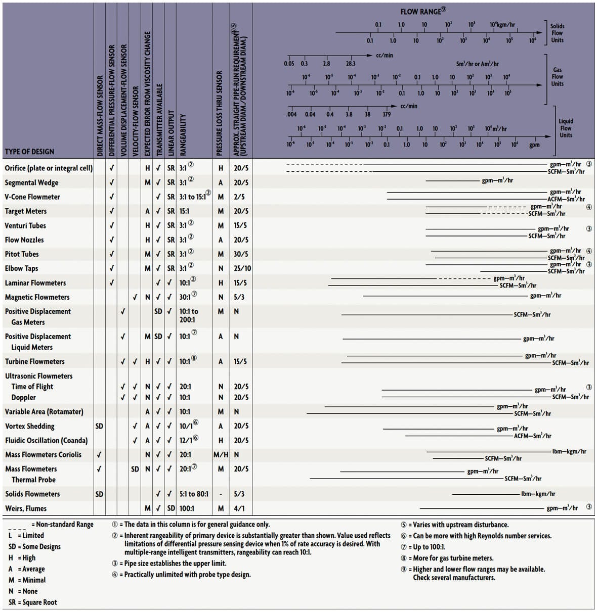
The pressure drops generated by a wide variety of geometrical restrictions have been well characterized over the years, and, as compared in Table 1, these primary or “head” flow elements come in a wide variety of configurations, each with specific application strengths and weaknesses. Variations on the theme of differential pressure (d/p) flow measurement include:
- Orifice
- Venturi / Flow Nozzle
- Rotameters / Variable Area
- Pitot Tubes
- When, in addition to measuring the flow, the process temperature or pressure is also to be measured, the pressure transmitter should not be installed in the process pipe but should be connected to the appropriate lead line of the flow element via a tee.
- The thermowell used for temperature measurement should be installed at least 10 diameters downstream of the flow element, to prevent velocity profile distortions.
- Welds should be ground smooth, and gaskets trimmed so that no protrusion can be detected by physical inspection.
 Table 1: Orientation Table for Flow Sensors
Primary Element Options
In the 18th century, Daniel Bernoulli, a Swiss mathematician and physicist, established “Bernoulli’s Equation” – which explains the relationship between static and kinetic energy in a flowing stream. As a fluid passes through a restriction, it accelerates, and the energy for this acceleration is obtained from the fluid’s static pressure. Consequently, the line pressure drops at the point of constriction (Figure 1). Part of the pressure drop is recovered as the flow returns to the unrestricted pipe.
 Figure 1: Orifice Plate Pressure Drop Recovery
The pressure differential (h) developed by the flow element is measured, and the velocity (V), the volumetric flow (Q), and the mass flow (W) can all be calculated using the following generalized formulas:
V = k (h/D)0.5
Or Q = kA (h/D)0.5
Or W = kA (hD)0.5
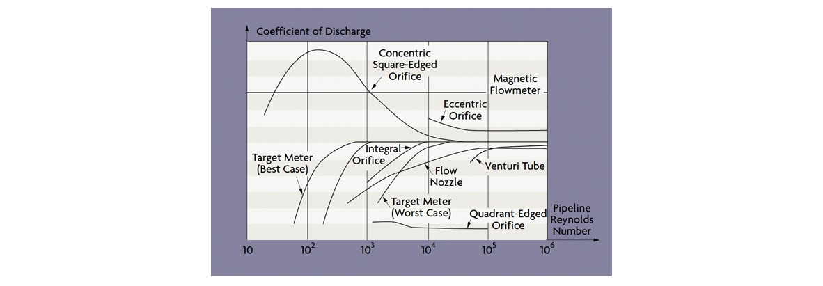
k is the discharge coefficient of the element (which also reflects the units of measurement), A is the cross-sectional area of the pipe’s opening, and D is the density of the flowing fluid. The discharge coefficient k is influenced by the Reynolds number (refer to Figure 2) and by the “beta ratio”, the ratio between the bore diameter of the flow restriction and the inside diameter of the pipe.
 Figure 2: Effect of Reynolds Numbers on Various Flow Meters
Additional parameters or correction factors can be used in the derivation of k, depending on the type of flow element used. These parameters can be computed from equations or read from graphs and tables available from the American National Standards Institute (ANSI), the American Petroleum Institute (API), the American Society of Mechanical Engineers (ASME), and the American Gas Association (AGA).
The discharge coefficients of primary elements are determined by laboratory tests that reproduce the geometry of the installation. Published values represent, generally, the average value for that geometry over a minimum of 30 calibration runs. The uncertainties of these published values vary from 0.5% to 3%. By using such published discharge coefficients, it is possible to obtain reasonably accurate flow measurements without in-place calibration. In-place calibration is required if testing laboratories are not available or if better accuracy is desired than that provided by the uncertainty range noted above. The relationship between flow and pressure drop varies with the velocity profile, which can be laminar or turbulent (Figure 1) as a function of the Reynolds number (Re), which for liquid flows can be calculated using the relationship:
Re = 3160(SG)(Q)/(ID)µ
Where ID is the inside diameter of the pipe in inches, Q is the volumetric liquid flow in gallons/minute, SG is the fluid specific gravity at 60oF, and µ is the viscosity in centipoises.
At low Reynolds numbers (generally under Re = 2,000), the flow is laminar, and the velocity profile is parabolic. At high Reynolds numbers (well over Re = 3,000), the flow becomes fully turbulent, and the resulting mixing action produces a uniform axial velocity across the pipe. As shown in Figure 2, the transition between laminar and turbulent flows can cover a wide range of Reynolds numbers; the relationship with the discharge coefficient is a function of the particular primary element.
Today, many engineering societies and organizations and most primary element manufacturers offer software packages for sizing d/p flow elements. These programs include the required data from graphs, charts, and tables as well as empirical equations for flow coefficients and correction factors. Some include data on the physical properties of many common fluids. The user can simply enter the application data and automatically find the recommended size, although these results should be checked for reasonableness by hand calculation.
Accuracy & Rangeability
The performance of a head-type flow meter installation is a function of the precision of the flow element and of the accuracy of the d/p cell. Flow element precision is typically reported in percentage of actual reading (AR) terms, whereas d/p cell accuracy is a percentage of calibrated span (CS). A d/p cell usually provides accuracy of ±0.2% of the calibrated span (CS). This means that, at the low end of a 10:1 flow range (at 10% flow), corresponding to a differential pressure range of 100:1, the flow meter would have an error of ±20% AR. For this reason, differential producing flow meters have historically been limited to use within a 3:1 or 4:1 range.
Flow meter rangeability can be further increased without adverse effect on accuracy by operating several d/p flow meters in parallel runs. Only as many runs are opened at a time as are needed to keep the flow in the active ones at around 75-90% of range. Another option is to stack two or more transmitters in parallel onto the same element, one for 1-10%, the other for 10-100% of full scale (FS) d/p produced. Both techniques are cumbersome and expensive. Intelligent transmitters offer a better option.
The accuracy of intelligent transmitters is usually stated as ±0.1% CS, which includes only errors due to hysteresis, rangeability, and linearity. Potential errors due to drift, temperature, humidity, vibration, overrange, radio frequency interference, and power supply variation are all excluded. If one includes them, inaccuracy is about 0.2% CS. Because intelligent d/p transmitters can – based on their own measurements – automatically switch ranges between two calibrated spans (one for 1-10%, the other for 10-100% of FS d/p), it should be possible to obtain orifice installations with 1% AR inaccuracy over a 10:1 flow range.
In most flow metering applications, density is not measured directly. Rather, it is assumed to have some normal value. If density deviates from this assumed value, error results. Density error can be corrected if it is measured directly or indirectly by measuring pressure in gases or temperature in liquids. Flow computing packages are also available that accept the inputs of the d/p transmitter and the other sensors and can simultaneously calculate mass and volumetric flow.
To minimize error (and the need for density correction) when dealing with compressible fluids, the ratio of differential pressure (h) divided by upstream pressure (P) should not exceed 0.25 (measured in the same engineering units).
Metering errors due to incorrect installation of the primary element can be substantial (up to 10%). Causes of such errors can be the condition of the mating pipe sections, insufficient straight pipe runs, and pressure tap and lead line design errors.
Under turbulent flow conditions, as much as 10% of the d/p signal can be noise caused by disturbances from valves and fittings, both upstream and downstream of the element, and by the element itself. In the majority of applications, the damping provided in d/p cells is sufficient to filter out the noise. Severe noise can be reduced by the use of two or more pressure taps connected in parallel on both sides of the d/p cell.
Pulsating flow can be caused by reciprocating pumps or compressors. This pulsation can be reduced by moving the flow meter away from the source of the pulse, or downstream of filters or other dampening instrumentation. Pulsation dampening hardware can also be installed at the pressure taps, or dampening software can be applied to the d/p cell output signal. One such filter is the inverse derivative algorithm, which blocks any rate of change occurring more quickly than the rate at which the process flow can change.
Piping, Installation, & Maintenance
Installation guidelines are published by various professional organizations (ISA, ANSI, API, ASME, AGA) and by manufacturers of proprietary designs. These guidelines include such recommendations as:
In order for the velocity profile to fully develop (and the pressure drop to be predictable), straight pipe runs are required both upstream and downstream of the d/p element. The amount of straight run required depends on both the beta ratio of the installation and on the nature of the upstream components in the pipeline. For example, when a single 90o elbow precedes an orifice plate, the straight-pipe requirement ranges from 6 to 20 pipe diameters as the diameter ratio is increased from 0.2 to 0.8.
In order to reduce the straight run requirement, flow straighteners (Figure 3) such as tube bundles, perforated plates, or internal tabs can be installed upstream of the primary element.
 Figure 3: Flow Straighteners Installed Upstream of Primary Element
The size and orientation of the pressure taps are a function of both the pipe size and the type of process fluid. The recommended maximum diameter of pressure tap holes through the pipe of flange is 1/4” for pipes under 2” in diameter, 3/8” for 2” and 3” pipes, 1/2” for 4 to 8” and 3/4” for larger pipes. Both taps should be of the same diameter, and, where the hole breaks through the inside pipe surface, it should be square with no roughness, burrs, or wire edges. Connections to pressure holes should be made by nipples, couplings, or adaptors welded to the outside surface of the pipe.
On services where the process fluid can plug the pressure taps or might gel or freeze in the lead lines, chemical seal protectors can be used. Connection sizes are usually larger (seal elements can also be provided with diaphragm extensions), and, because of the space requirement, they are usually installed at “radius tap” or “pipe tap” locations, as shown in Figure 4. When chemical seals are used, it is important that the two connecting capillaries, as they are routed to the d/p cell, experience the same temperature, and are kept shielded from sunlight.
 Figure 4: Differential Pressure Tap Location Alternatives
The d/p transmitter should be located as close to the primary element as possible. Lead lines should be as short as possible and of the same diameter. In clean liquid service, the minimum diameter is 0.4”. In steam service, the horizontal lead lines should be kept as short as possible and be titled (with a minimum gradient of 1 in/ft with respect to the piping) towards the tap, so that condensate can drain back into the pipe. Again, both lead lines should be exposed to the same ambient conditions and be shielded from sunlight. In clean liquid or gas service, the lead lines can be purged through the d/p cell vent or drain connections, and they should be flushed for several minutes to remove all air from the lines. Entrapped air can offset the zero calibration.
Seal pots are on the wet leg in d/p cell installations with small ranges (under 10 in H20) in order to minimize the level variation in the legs. In steam applications, filling tees are recommended to ensure equal height condensate legs on both sides of the d/p cell. If for some reason the two legs are not of equal height, the d/p cell can be biased to zero out the difference as long as that difference does not change.
If the process temperature exceeds the maximum temperature limitation of the d/p cell, either chemical seals have to be used or the lead lines need to be long enough to cool the fluid. If a large temperature drop is required, a coiled section of tubing (pigtail) can be installed in the lead lines to cool the process fluids.
The frequency of inspection or replacement of a primary element depends on the erosive and corrosive nature of the process and on the overall accuracy required. If there is no previous experience, the orifice plate can be removed for inspection during the first three, six, and 12 months of its operation. Based on visual inspection of the plate, a reasonable maintenance cycle can be extrapolated from the findings. Orifices used for material balance calculations should be on the same maintenance cycle.

