Appelez-nous au 1-888-826-6342
Variable Area In-line Flow Meters For Air
Variable Area In-line Pneumatic Flow Meters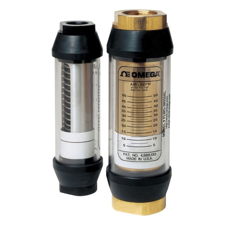
Ajouté à votre panier
Configuration terminée.
Veuillez ajouter au panier pour la conserver ou quitter la configuration
Veuillez ajouter au panier pour la conserver ou quitter la configuration
Échec de l'enregistrement des configurations, cliquez sur le bouton Configurer Recommencer
- Monitoring Most Pneumatic or Compressed Gas Systems
- Flow Rates From 1 to 900 SCFM @ 100 psi
- High Pressure: to 600 psi for Brass or Aluminum, 1000 psi for Stainless Steel
- High Temperature—to 116°C (240°F) Standard, 204 or 316°C (400 or 600°F) Optional
FLMG-10050AL Options de modèles
Voir tous les modèlesModifiez ces spécifications pour commander un modèle différente. Toutes les combinaisons ne sont pas valides. Les options compatibles avec les sélections précédentes seront en gras.
*Les options en surbrillance ne sont pas compatibles. Veuillez sélectionner une combinaison différente.
Gas Flow Range
Process Connection Size
Wetted Materials
Max Operating Pressure
Features
Category
Media Type
Liquid Flow Range
Accuracy
Process Connection Type
Max Process Temperature
Scale
Valve Included
The FLMG flow meters feature rugged construction, easy installation, and direct-reading flow rates of air. The units are calibrated at 100 psi pressure, suitable for most compressed pneumatic applications.
The spring-and-piston type assembly enables these flow meters to be mounted in any position. The FLMG models with optional analog output (-MA) are typically used to transmit a signal proportional to the flow rate to a process controller, a PLC, a recorder, or a panel-mount display. With the -MA option, the user can choose between reading a 0 to 2000 Hz square-wave pulse, a 0 to 5 Vdc analog signal, or a 2-wire 4 to 20 mA analog signal by connecting the appropriate pins.
SPECIFICATIONS
Measuring Accuracy: ±4% FS over the entire scale range
Repeatability: ±1% FS
Flow Measuring Range: 1.2 to 900 SCFM
Maximum Operating Pressure:
Aluminum and Brass Monitors: 40 bar (600 psig)
Stainless Steel Monitors: 70 bar (1000 psig) up to 116°C (240°F)
Maximum Operating Temperature: 116°C (240°F)
Note: For options “-HT” and “-UHT”, see high-temperature graph on spec sheet
Pressure Differential: See the pressure graphs on spec sheet.
Standard Calibration Fluids: Air @ 21°C (70°F), 1.0 sg and 6.8 bar (100 psig)
Relay (Optional): 1 or 2 form “C” relays, rated 10 A, 125 or 250 Vac or ¼ A, 250 Vdc
Mechanical Life: >106 cycles
Analog Output (Optional): Supply voltage 12 to 35 Vdc, field selectable for 0 to 5 Vdc (100 W minimum load), 0 to 2000 Hz square-wave pulse or 4 to 20 mA
Rmax = 50 (Vs - 12)
(Vs = supply voltage DC)
Installation Dimensions:
1/4 and 1/2 NPT Sizes: 1-7/8 OD x 6-9/16" length
3/4 and 1 NPT Sizes: 2-3/8 OD x 7-5/32" length
1-1/4 and 1-1/2 NPT Sizes: 3-1/2 OD x 10-1/8" length
| Description | Aluminum | Brass | Stainless Steel |
| High pressure casing, end ports and tapered shaft | Aluminum | Brass | 304 SS |
| Seals | Buna (std), EPR, FKM or perfluoroelastomer | Buna (std), EPR, FKM or perfluoroelastomer | FKM with PTFE backup (std) Buna, EPR or perfluoroelastomer |
| Transfer Magnet | PTFE-coated Alnico | PTFE-coated Alnico | PTFE-coated Alnico |
| Floating Orifice Disk | Stainless Steel | Stainless Steel | Stainless Steel |
| All Other Internal Parts | Stainless Steel | Stainless Steel | Stainless Steel |
| Description | Aluminum | Brass | Stainless Steel |
| Window Tube | Polycarbonate (std), Pyrex® | Polycarbonate (std), Pyrex® | Polycarbonate (std), Pyrex® |
| Window Seals | Buna (std) | Buna (std) | Buna (std) |
Rated 4 out of
5
by
Masood from
Good product
I just bought this and I am happy so far with its performance.
Date published: 2017-10-08
 RoHS 2015/863 - Voir le certificat
 Approuvé CE