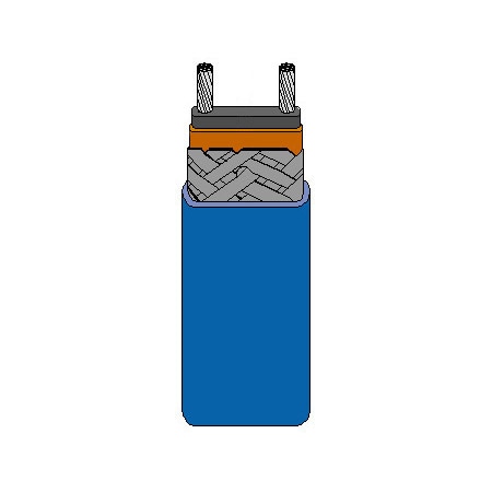
No one heat trace fits all. In almost all cases, heat traces need customization based on the pipe or vessel setup. Designing a perfect heat trace system requires considering several important variables.
Below is a step-by-step guide to designing a heat trace system. Note that the procedure mentioned here is a reference guide only. We recommend consulting Omega Engineering to get accurate formulas and data.
Step 1: Calculate the Heat Loss
The first step in creating a heat trace is to understand the amount of heat loss happening within each pipe. To calculate heat loss, you will require the following data points.
- Minimum ambient temperature
- Maintenance temperature
- Location of the pipe or vessel (indoor or outdoor)
- Thermal insulation of the pipes
Step 2: Adjustment for Insulation
Now that we have some initial data, we need to adjust values based on insulation. Multiplying heat loss with the insulation adjustment factor will provide heat loss adjusted with respect to the insulation material. You can get the insulation data for a specific cable literature.
Step 3: Correct for Location/Wind Speed
The next step is to factor in wind speed. Of course, wind speed will not apply to all setups. However, in places where the wind affects the temperature of the pipe, it needs to be counted in. The general rule of thumb for an indoor setup is to multiply the heat loss value after insulation adjustment by 0.9.
Step 4: Correct for Additional Safety Factor
The last steps are about factoring variables like heat loss from additional equipment such as valves, flanges, etc., or other safety factors that would impact the temperatures.


