RTD Types
 The invention of a resistance thermometer was made possible by the discovery that the conductivity of metals decreases predictably with increases in their temperatures. The first-ever resistance thermometer was assembled from insulated copper wire, a battery, and a galvanometer in 1860. However, its inventor, C.W. Siemens, soon discovered that a platinum element yielded more accurate readings at a much wider range of temperatures.
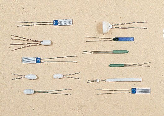
RTDs available today can generally be categorized into one of two basic types, depending on how their temperature sensing element is constructed. One type of RTD contains wire-wound elements and the other type of RTD contains thin-film elements. Each type is best suited for use in certain environments and applications.
Wire-Wound RTDs
In the wire-wound type of RTD, the sensing element is comprised of a small coil of ultra-thin wire (typically platinum). This wire coil can be packaged inside a ceramic or glass tube (the most common construction) or the wire can be wound around the outside of a ceramic or glass housing material. Wire-wound RTD sensing elements can easily be made into Pt100 probes by mounting them inside metal tubes or sheaths. This protects them from their surroundings and increases their durability. They can also be fitted into custom housings.Wire-wound RTDs (especially the inner-coil type) are the most accurate type of RTD. Those with glass cores can readily be immersed in many liquids, while those with ceramic cores can be used to accurately measure extremely high temperatures. However, they are more expensive to manufacture than thin-film types, requiring skilled labor and advanced assembly facilities. They also tend to be more vibration sensitive.
Thin-Film RTDs
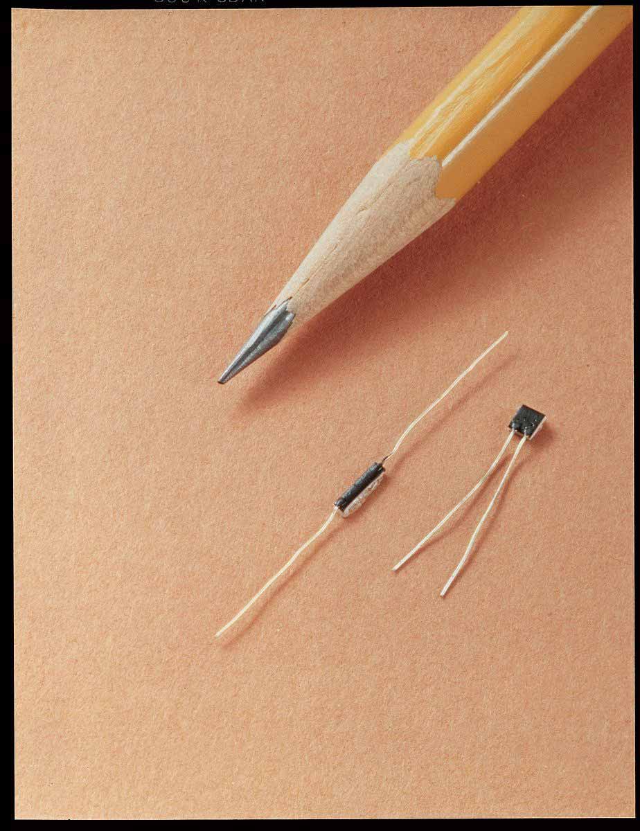
Thin-film RTD elements are made by depositing a very thin layer of metal (usually platinum) onto a ceramic substrate material. The metal film is laser cut or etched into an electrical circuit pattern that provides the specified amount of resistance.Lead wires are then attached, and a thin protective glass coating is applied to the entire element.
This type of RTD is popular because of its ruggedness, reliability, and low cost. Thin-film elements are more resistant to damage from shock or vibration than other types of RTDs. Their flat profile makes for design flexibility, enabling their use in many different industrial control and instrumentation applications. Multiple resistance, tolerance, size, and shape options are also available.
In these types of RTDs, a platinum or metal-glass slurry film is deposited or screened onto a small flat ceramic substrate, etched with a laser trimming system, and sealed. The film RTD offers substantial reduction in assembly time and has the further advantage of increased resistance for a given size. Due to the manufacturing technology, the device size itself is small, which means it can respond quickly to step changes in temperature. Film RTDs are presently less stable than their hand-made counterparts, but they are becoming more popular because of their decided advantages in size and production cost. These advantages should provide the impetus for future research needed to improve stability.
Material of Resistance Element
Several metals are quite common for use in resistance elements and the purity of the metal affects its characteristics. Platinum is by far the most popular due to its linearity with temperature. Other common materials are nickel and copper, although these are being replaced by platinum elements.Metals
All metals produce a positive change in resistance for a positive change in temperature. This, of course, is the main function of an RTD sensor. As we shall soon see, system error is minimized when the nominal value of the RTD resistance is large. This implies a metal wire with a high resistivity. The lower the resistivity of the metal, the more material we will have to use. The following table lists the resistivities of common materials for a resistance thermometer.| METAL | RESISTIVITY | |
| Gold | Au | 13.00 |
| Silver | Ag | 8.8 |
| Copper | Cu | 9.26 |
| Platinum | Pt | 59.00 |
| Tungsten | W | 30.00 |
| Nickel | Ni | 36.00 |
Platinum Resistance Temperature Detectors
Platinum is the most common material used for resistance elements in RTDs for industrial applications due to its high accuracy, linearity with temperature, long term stability, and excellent resistance to corrosion. In addition, platinum RTDs are resistant to corrosion and oxidation and can measure a wide temperature range.Nickel Resistance Temperature Detectors
Nickel is also used as a resistance element for RTDs in industrial applications. Nickel RTDs have good corrosion resistance and are less expensive than platinum RTDs, but nickel ages rapidly and, over time, they lose their accuracy.Copper Resistance Temperature Detectors
Copper is a popular material used for resistance elements in RTDs for industrial applications due to its superior electrical conductivity, corrosion resistance, and low cost of production. Copper also has a wide range of temperatures in which it can provide accurate measurements, making it ideal for a variety of industrial applications. However, copper is also susceptible to oxidation and can become brittle due to exposure to extreme temperatures. Additionally, copper is a soft metal, making it more susceptible to damage from vibration and mechanical stress, which can lead to inaccurate readings.Resistance Element Characteristics
 There are several very important details that must be specified in order to properly identify the characteristics of the RTD:
- Material of Resistance Element (Platinum, Nickel, etc.)
- Temperature Coefficient
- Nominal Resistance
- Temperature Range of Application>
- Physical Dimensions or Size Restrictions
- Accuracy
Temperature Coefficient
The temperature coefficient of an element is a physical and electrical property of the material. This is a term that describes the average resistance change per unit of temperature from ice point to the boiling point of water. Different organizations have adopted different temperature coefficients as their standard. In 1983, the IEC (International Electrotechnical Commission) adopted the DIN (Deutsche Institute for Normung) standard of Platinum 100 ohm at 0 oC with a temperature coefficient of 0.00385 ohms per ohm degree centigrade. This is now the accepted standard of the industry in most countries, although other units are widely used.A quick explanation of how the coefficient is derived is as follows:
-
Resistance at the boiling point (100 oC) = 138.50 ohms
Resistance at ice point (0 oC) = 100.00 ohms
Divide the difference (38.5) by 100 degrees and then divide by the 100 ohm nominal value of the element
The result is the mean temperature coefficient (alpha) of 0.00385 ohms per ohm oC
- Pt TC = .003902 (U.S. Industrial Standard)
- Pt TC = .003920 (Old U.S. Standard)
- Pt TC = .003923 (SAMA)
- Pt TC = .003916 (JIS)
- Copper TC = .0042
- Nickel TC = .00617 (DIN)
- Nickel TC = .00672 (Growing less common in U.S.)
- Balco TC = .0052
- Tungsten TC = .0045
Nominal Resistance
Nominal Resistance is the prespecified resistance value at a given temperature. Most standards, including IEC-751, use oC as their reference point. The IEC standard is 100 ohms at 0 oC, but other nominal resistances, such as 50, 200, 400, 500, 1000, and 2000 ohm, are available.Temperature Range of Application
Depending on the mechanical configuration and manufacturing methods, RTDs may be used from -270 oC to 850 oC. Specifications for temperature range will be different for different types (i.e., thin film, wire wound, and glass encapsulated).Physical Dimensions or Size Restrictions
The most critical dimension of the element is outside diameter (O.D.), because the element must often fit within a protective sheath. The film type elements have no O.D. dimension. To calculate an equivalent dimension, we need to find the diagonal of an end cross section (this will be the widest distance across the element as it is inserted into a sheath).For example, using an element that is 10 x 2 x 1.2 mm, the diagonal can be found by taking the square root of (22 + 1.52). Thus, the element will fit into a 2.5 mm (0.98”) inside diameter hole. For practical purposes, remember that any element 2 mm wide or less will fit into a 1/8” O.D. sheath with 0.010” walls, generally speaking. Elements which are 1.5 mm wide will typically fit into a sheath with 0.084” bore (refer to Figure 1.)
Accuracy
IEC 751 specifications for Platinum Resistance Thermometers have adopted DIN 43760 requirements for accuracy. DIN-IEC Class A and Class B elements are shown on Figure 2 and Figure 3.Response Time
50% response is the time the thermometer element needs in order to reach 50% of its steady state value. 90% response is defined in a similar manner. These response times of elements are given for water flowing with 0.2 m/s velocity and air flowing at 1 m/s. They can be calculated for any other medium with known values of thermal conductivity. In a 1/4” diameter sheath immersed in water flowing at 3 feet per second, response time to 63% of a step change in temperature is less than 5.0 seconds.Measurement Current and Self-Heating
Temperature measurement is carried out almost exclusively with direct current. Unavoidably, the measuring current generates heat in the RTD. The permissible measurement currents are determined by the location of the element, the medium which is to be measured, and the velocity of moving media. A self-heating factor, “S”, gives the measurement error for the element in oC per milliwatt (mW). With a given value of measuring current, “I”, the milliwatt value “P” can be calculated from P = I2R, where “R” is the RTD’s resistance value. The temperature measurement error Δ T (ºC) can then be calculated from Δ T = P x S.Resistance Element Specifications
- Stability: Better than 0.2 oC after 10,000 hours at maximum temperature (1 year, 51 days, 16 hours continuous)
- Vibration Resistance: 50 g @ 500 oC; 200 g @ 20 oC; at frequencies from 20 to 1000 cps
- Temperature Shock Resistance: In forced air: over entire temperature range In a water quench: from 200 to 20 oC
- Pressure Sensitivity: Less than 1.5 x 10⁻⁴ C/PSI, reversible Self-Heating Errors & Response Times: Refer to specific Temperature Handbook pages for the type of element selected
- Self-Inductance from Sensing Current: Can be considered negligible for thin film elements; typically less than .02 microhenry for wire wound elements
- Capacitance: For wire wound elements: calculated to be less than 6 PicoFarads; for film-type elements: capacitance is too small to be measured and is affected by lead wire connection. Lead connections with element may indicate about 300 pF capacitance.

