RTD probes come in a variety of configurations, including 2-wire, 3-wire, and 4-wire models. There are significant differences between these types, and these differences must be taken into consideration when selection the appropriate device for an application.
Factors to Consider
When deciding between 2-wire, 3-wire, and 4-wire RTD sensors, there are several factors to be considered, including:Environmental Factors
Certain environmental factors, such as high levels of electrical noise or interference, cause disturbances that can result in measurement errors.Application Requirements
Different applications require different thresholds of accuracy. It is absolutely imperative that a sensor offers sufficient accuracy for that specific application.Budget Limitations
Cost is an important consideration when selecting an RTD for any specific application. As there are more components involved with a 4-wire configuration, 4-wire RTDs tend to be more expensive than 2- wire or 3-wire RTDs.RTD Wire Configuration Types
How an RTD circuit is configured determines how accurately the sensor’s resistance can be calculated as well as how much the temperature reading may be distorted by extraneous resistance in the circuit.Each of the three configuration types, 2-wire, 3-wire, and 4-wire, has its own advantages and disadvantages, and selecting the right configuration is dependent on the application. By understanding the characteristics of each configuration, engineers and technicians can ensure that the RTD sensor is used most effectively.
2-Wire Configuration
The 2-wire RTD configuration is the simplest among the RTD circuit designs. In this serial configuration, a single lead wire connects each end of the RTD element to the monitoring device. Because the resistance calculated for the circuit includes the resistance between wires and RTDconnectors as well as the resistance in the element, the result will always contain some degree of error.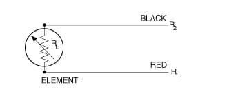
The circle represents the element boundaries to the point of calibration. The resistance RE is taken from the resistance element and is the value that will supply us with an accurate temperature measurement. Unfortunately, when we take our resistance measurement, the instrument will indicate RTOTAL:
Where RT = R1 + R2 + R3
This will produce a temperature readout higher than that actually being measured. Although the use of high-quality tests leads and connectors can reduce this error, it is impossible to eliminate it entirely.
As a result, 2-wire RTD configuration is most useful when used with high-resistance sensors or in applications where e a great deal of accuracy is not required.
3-Wire Configuration
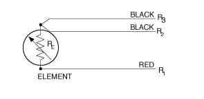 The 3-wire RTD configuration is the most commonly used RTD circuit design and can be seen in industrial process and monitoring applications. In this configuration, two wires link the sensing element to the monitoring device on one side of the sensing element, and one links it on its other side.
If three identical type wires are used and their lengths are equal, then R1 = R2 = R3. By measuring the resistance through leads 1 and 2 as well as through the resistance element, a total system resistance is measured (R1 + R2 + RE).
If the resistance is also measured through leads 2 and 3 (R2 + R3), we obtain the resistance of just the lead wires, and since all lead wire resistances are equal, subtracting this value (R2 + R3) from the total system resistance (R1 + R2 + RE) leaves us with just RE, and an accurate temperature measurement has been made.
Because this is an averaged result, the measurement will be accurate only if all three connecting wires have the same resistance.
4-Wire Configuration
This configuration is the most complex and thus the most time-consuming and expensive to install, but it produces the most accurate results.
The bridge output voltage is an indirect indication of the RTD resistance. The bridge requires four connection wires, an external source, and three resistors that have zero temperature coefficient. To avoid subjecting the three bridge-completion resistors to the same temperature as the RTD sensor, the RTD is separated from the bridge by a pair of extension wires.
These extension wires recreate the problem that we had initially: the impedance of the extension wires affects the temperature reading. This effect can be minimized by using a three-wire bridge configuration.
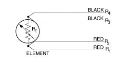
In a 4-wire RTD configuration, two wires link the sensing element to the monitoring device on both sides of the sensing element. One set of wires delivers the current used for measurement, and the other set measures the voltage drop over the resistor.
With the 4-wire configuration, the instrument will pass a constant current (I) through the outer leads, 1 and 4.
The RTD Wheatstone bridge creates a non-linear relationship between resistance change and bridge output voltage change. This compounds the already non-linear temperature-resistance characteristic of the RTD by requiring an additional equation to convert bridge output voltage to equivalent RTD impedance.
The voltage drop is measured across the inner leads, 2 and 3. So, from V = IR, we learn the resistance of the element alone, with no effect from the lead wire resistance. This offers an advantage over 3-wire configurations only if dissimilar lead wires are used, and this is rarely the case.
This 4-wire bridge design fully compensates for all resistance found in the lead wires and the connectors between them. A 4-wire RTD configuration is primarily used in laboratories and other settings where great accuracy is necessary.
2-Wire Configuration with a Closed Loop
Another configuration option, albeit one that is now rare, is a standard 2-wire configuration with a closed loop of wire alongside it. This configuration functions the same as a 3-wire configuration but uses an additional wire to do so. A separate pair of wires is provided as a loop to provide compensation for lead resistance and ambient changes in lead resistance.Conclusion
RTD configurations are an invaluable tool in the industrial world - capable of meeting most accuracy requirements. With the correct configuration selection, RTD probes can provide accurate measurements and are reliable and repeatable in a wide range of harsh environments. To get the best results, it is important to have a full understanding of the different types of wire configurations available and choose the one that best suits the application's needs. With the correct configuration, an RTD sensor is capable of providing accurate and reliable temperature measurements.
Product Info

What is a Calibrator and why is it an important device? Introduction to Instrument Calibration
Technical Learning