Skip to search Skip to main content Skip to navigation

PST joins DwyerOmega. Read more>

We noticed you are from . Visit your local site for regional offers and live support.

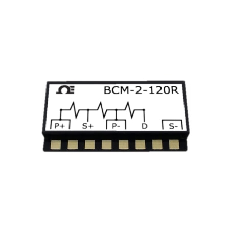
Compact Strain Gauge Bridge Completion Module

120 Ω Resistor network
Warranty
  • RoHS Icon

C$164.82

Item# BCM-2-120R

Volume discounts available
Volume Discount Schedule
Quantity Price each
1-4 C$164.82
5-9 C$156.58
10-24 C$153.28
25-49 C$146.69
50-99 C$143.39
100+ C$140.10

In stock

Lead Time (If not in stock): 11 weeks
120 Ω Resistor network BCM-2-120R BCM-2-120R
  • Easy to Use
  • Ultra Low TCR
  • Ultra High Precision, Accuracy, and Stability
  • Compact size

BCM-2-120R Model Options

View all models

Edit these specs to order a different model. Not all combinations are valid. Options compatible with previous selections will be in bold.

*Highlighted options are not compatible. Please select a different combination.

Resistance
Features


An external bridge completion module must be used when instrumentation is not designed to measure a strain gauge directly. The BCM-2 Series employs metal-foil resistance elements bonded to a ceramic substrate. The packaging protects the resister circuitry and ensures long-term stability; in most cases, no additional protection is required, facilitating field use. The BCM-2 resistance elements are matched with each other and match the ceramic's thermal expansion coefficient, resulting in a low temperature coefficient of resistance (TCR).

Each module is marked with a circuit/wiring diagram for easy terminal identification and foam tape for easy attachment to the test-part surface or near the instrumentation site. Heavy, pre-tinned copper terminals facilitate the attachment of up to 22 AWG (0.64mm diameter) lead wires.

Completing a bridge circuit adjacent to the strain gage site creates a stable simple voltage differantial systme between the strain gage circuit and the instrumentation. Co-locating the strain gauges and BCM-2 also reduces the potetional for noise pickup in the lead wire system especially in situations where switch contacts, slip rings, or other mechanical connections are employed between the strain gages and instrumentation.

Cross to Vishay/Micro-Measurements MR1-350-130 & MRF-350-130

Part number Resistor Value
BCM-2-120R 120 Ω
BCM-2-350R 350 Ω

loading all models
loading all reviews
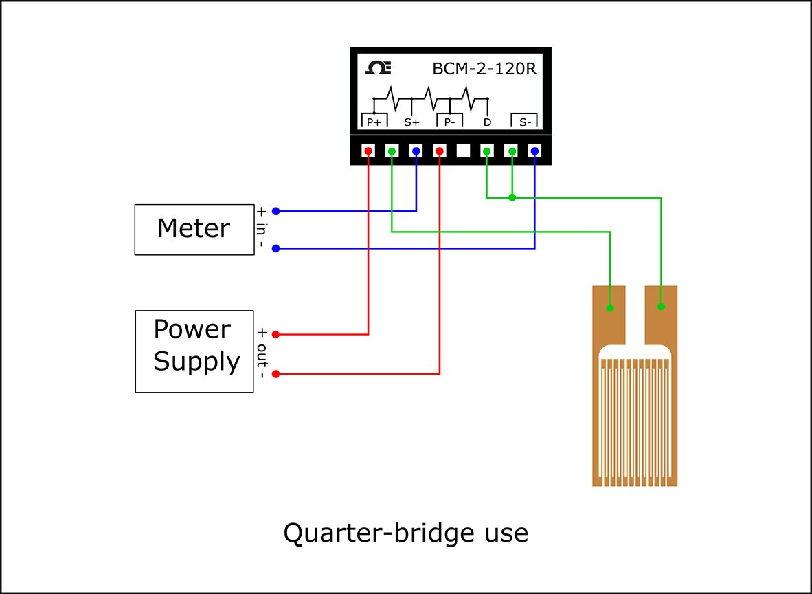
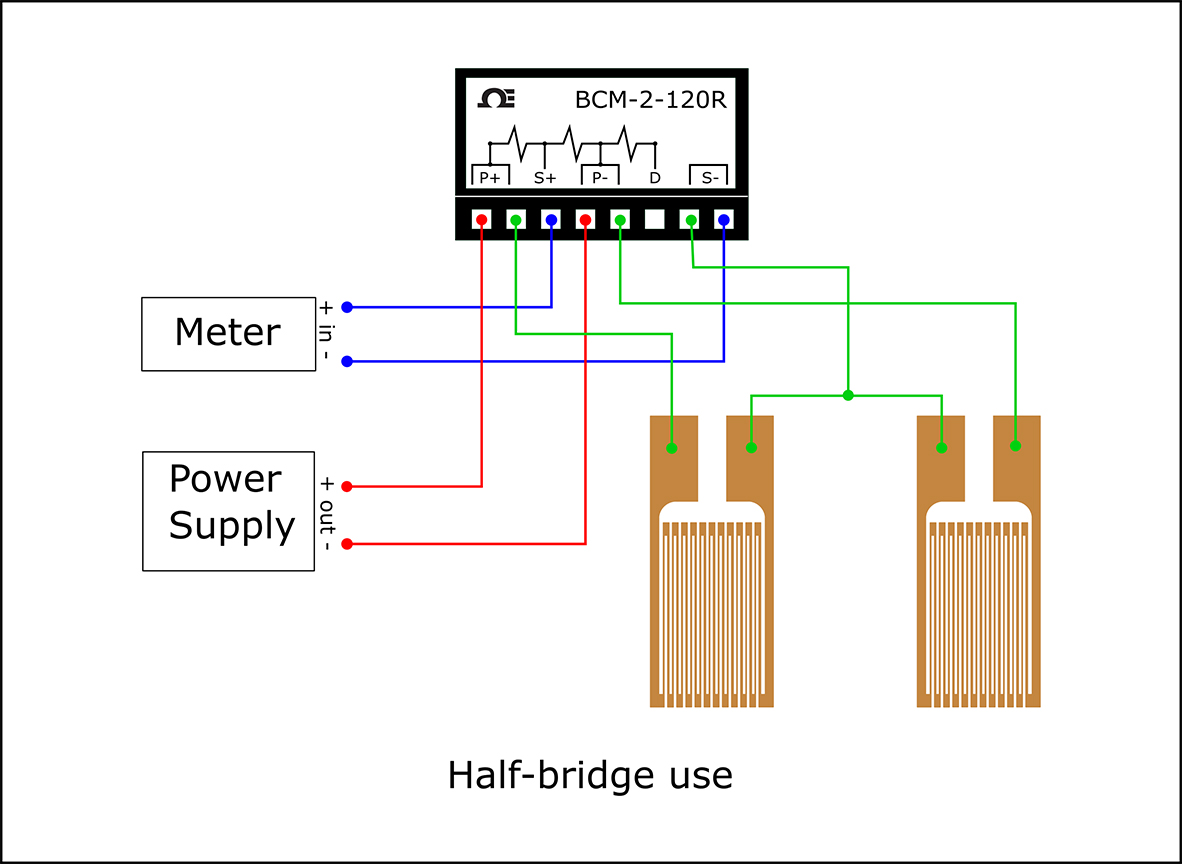
Rated 5 out of 5 by from Successful connections and readings. I was able to attach connecting wires to the terminals easily. With a soldering iron, I connected the wires. Using the circuit diagrams online, I completed the connection with a DC power supply, a meter, and the 120 ohm strain gauge. I'm getting good readings so far!
Date published: 2024-04-25
Rated 5 out of 5 by from EZPZ Works great! Takes the guesswork out of a wheatstone bridge
Date published: 2022-11-14
  • y_2024, m_12, d_13, h_8
  • bvseo_bulk, prod_bvrr, vn_bulk_3.0.42
  • cp_1, bvpage1
  • co_hasreviews, tv_0, tr_2
  • loc_en_CA, sid_BCM-2-120R, prod, sort_[SortEntry(order=HELPFULNESS, direction=DESCENDING), SortEntry(order=POSITIVE_FEEDBACK, direction=DESCENDING), SortEntry(order=SUBMISSION_TIME, direction=DESCENDING)]
  • clientName_omega
  • bvseo_sdk, java_sdk, bvseo-4.0.0
  • CLOUD, getReviews, 6ms
  • REVIEWS, PRODUCT
loading all QA

what are the power supply requirements for this module? how come there is no specification sheet or manual available for this product?

Asked by: serg10
There is no power specification for the BCM-2. The is simply a bridge completion circuit for use with strain gages. The excitation voltage applied to the P+ and P- terminal depends on the maximum allowable excitation of the particular strain gage you are using with the BCM-2. This value varies with the size and resistance of the strain gages
Answered by: JK Applications Engineer
Date published: 2024-09-16

What is the pitch between the solder pads?

Asked by: tb123
Hello, I have contacted our engineering team for this information. Can you kindly email us at pressure@omega.com? I can forward you the response as soon as I hear from them. Thank you.
Answered by: SAE JK
Date published: 2024-10-27

If one wanted to shunt calibrate one of these devices, which terminals should the shunt resistor be placed?

Asked by: Wyman
Thank you for your inquiry, shunt calibration is usually connected across the negative excitation and the negative output terminals
Answered by: rkent
Date published: 2022-10-28
  • y_2024, m_12, d_12, h_7CST
  • bvseo_bulk, prod_bvqa, vn_bulk_3.0.42
  • cp_1, bvpage1
  • co_hasquestionsanswers, tq_3
  • loc_en_CA, sid_BCM-2-120R, prod, sort_[SortEntry(order=NUM_ANSWERS, direction=DESCENDING)]
  • clientName_omega
  • bvseo_sdk, java_sdk, bvseo-4.0.0
  • CLOUD, getContent, 33ms
  • QUESTIONS, PRODUCT

Related Categories

en-CA
en
Save Configuration