Skip to search Skip to main content Skip to navigation

Call us at 1-888-826-6342
We noticed you are from . Visit your local site for regional offers and live support.

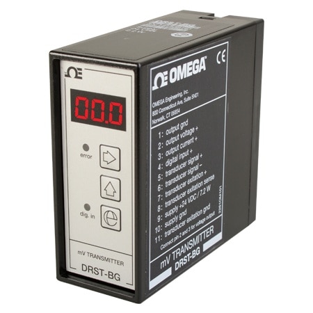
DIN RAIL Signal Conditioner for Load Cells

Signal Transmitter for Load Cell & Strain Gage Application
Warranty
  • RoHS Icon

C$722.57

Item# DRST-BG

Volume discounts available
Volume Discount Schedule
Quantity Price each
1-4 C$722.57
5-9 C$686.44
10-24 C$671.99
25-49 C$643.09
50-99 C$628.64
100+ C$614.18

In stock

Lead Time (If not in stock): 12 weeks
Signal Transmitter for Load Cell & Strain Gage Application DRST-BG DRST-BG
  • Load cell & Strain Gage Amplifier
  • MV to Current/Voltage Conversion
  • Front-Programmable/LED Display
  • Relative Calibration of Input Span

DRST-BG Model Options

View all models

Edit these specs to order a different model. Not all combinations are valid. Options compatible with previous selections will be in bold.

*Highlighted options are not compatible. Please select a different combination.

Input Type
Input Class
Input Ranges
Output Type
Output Class
Display Type
Supply Voltage Type
Isolation
Programability


Brand New DRST-BG MV Signal Transmitter converts bipolar mV signals from transducers supplied directly by the device to standard current/voltage signals.

Application
DRST-BG is suitable for load cell application as well as other applications such as tank filling and draining, weighing with a taring function, measurement of cable tensile force, level control, signal conversion/amplification.
Advanced Features
A multifunction user interface consisting of three push buttons and a 3-digit LED display for programming.
Technical Characteristics
    • Front error LED.
    • The analog input can be programmed for voltage in the range -40 to 100 m Vdc.
    • The digital signal can be selected as either NPN or PNP. Taring can either be by way of the digital input or from the front interface.
    • The analog output can be programmed to current in the range 0 to 20 mA or voltage in the range     • Short circuit protected transducer supply which can be programmed to 5 to 13 Vdc from the front.
    • Sense input (with transducer supply used) for compensation for cable resistance to the transducer.
    • Mounting for a standard 11-pole socket which can be adapted for DIN rail or plate.

Specifications

Environmental Conditions
Operating Temperature: -20 to 60°C
Calibration Temperature: 20 to 28°C
Relative Humidity: < 95% RH (non-cond.)
Protection Degree: IP50

Mechanical Specifications
Dimensions (HxWxD): 80.5 x 35.5 x 84.5 mm (D is without pins)
Weight Approx: 130 g

Common Specifications
Supply Voltage: 19.2 to 28.8 Vdc
Max. Required Power: 7.2 W
Internal Power Dissipation: 2.2 W
Response Time (Programmable): 0.06 to 999 s
Signal/Noise Ratio: Min. 60 dB
Updating Time: 20 ms
Signal Dynamics, Input: 17 bit
Signal Dynamics, Output: 16 bit
Effect of Supply Voltage Change: < ±0.002% of span/%V
Temperature Coefficient: < ±0.01% of span/°C
Linearity Error: < 0.1% of span
Auxiliary Voltage: Transducer
Supply: 5 to 13 Vdc
Load (Max.): 230 mA
EMC Immunity Influence: < ±0.5% of span

Input Specifications
Common Input Specifications
Max. Offset: 70% of selec. max. value
Voltage input
Measurement Range: -40 to 100 mV
Min. Measurement Range (Span): 10 mV
Input Resistance: > 10 MO
Overrange: 0 to 999% of selected measurement range
NPN, Digital Input: Pull up 24 Vdc / 6.9 mA
PNP, Digital Input: Pull down 0 Vdc/6.9 mA
Trig Level Low, NPN/PNP: < 6 Vdc
Trig Level High, NPN/PNP: > 10.5 Vdc
Pulse Length: > 30 ms

Output Specifications
Current Output
Signal Range: 0 to 20 mA
Min. Signal Range: 5 mA
Load (@ Current Output): = 600 Ω
Load Stability:= 0.01% of span/100 Ω
Current Limit: < 23 mA
Voltage Output Through Internal
shunt: See manual for details
Of Span: = of the presently selected range

Observed Authority Requirements
EMC 2014/30/EU
EAC: TR-CU 020/2011
loading all models
loading all reviews
  • bvseo_sdk, java_sdk, bvseo-4.0.0
  • CLOUD, getReviews, 4ms
  • REVIEWS, PRODUCT
  • bvseo-msg: The resource to the URL or file is currently unavailable.;
loading all QA

How would I connect wires to this signal conditioner? Are there screw terminals on the back?

Asked by: plxprt_RDC
There are a series of numbered screw terminals on the back of this unit. They are identified by a table printed on the side of the case and also in the user's manual.
Answered by: JK Applications Engineer
Date published: 2024-10-03
  • y_2024, m_10, d_6, h_4CST
  • bvseo_bulk, prod_bvqa, vn_bulk_3.0.42
  • cp_1, bvpage1
  • co_hasquestionsanswers, tq_1
  • loc_en_CA, sid_DRST-BG, prod, sort_[SortEntry(order=NUM_ANSWERS, direction=DESCENDING)]
  • clientName_omega
  • bvseo_sdk, java_sdk, bvseo-4.0.0
  • CLOUD, getContent, 9ms
  • QUESTIONS, PRODUCT
en-CA
en
Save Configuration