A Data Acquisition (DAQ) system that measures current typically does so directly. However, DAQ systems that measure voltage are often more readily available to the user. This technique requires the current to be converted into voltage so the voltage DAQ system can read the signal. An electrical shunt can perform this task, but it requires a system with a high input impedance. The best shunt to use also requires calculates based on standard formulas.
 Voltage Input
Input Impedance
Electrical impedance is generally a measure of a circuit’s opposition to a current when a voltage is applied to it. Input impedance is the impedance of a load network from a source network, including both static and dynamic opposition. Static opposition is more commonly known as resistance, while dynamic electrical opposition is known as reactance. A load network is the portion of an electrical network that consumes power, whereas a source network is the portion that transmits power. The source network’s output impedance and load network’s input impedance determine how current and voltage change when power is transferred from the source to the load network.
Impedance is often used to evaluate a network’s electrical efficiency, which is generally the ratio of useful power output to total power input. This process typically involves breaking the network into stages and obtaining the input and output impedance between the stages. Within the context of impedance, efficiency is the ratio of the input impedance to the total impedance, which is the sum of the input impedance and output impedance. The reactance component of impedance often results in significant power losses for AC circuits. These losses can result in a phase imbalance, meaning that the circuit’s current is therefore less than it would be if the current and voltage were in phase, since power is the product of current voltage. DC circuits don’t have reactance, so they don’t suffer from this type of power loss.
DAQ Systems
Data Acquisition (DAQ) is the process of sampling electrical signals, typically those that measure physical conditions. These systems generally consist of three components:
- Sensors
- Signal Conditioning Circuitry
- Analog-to-Digital Converter
The sensors convert physical parameters into an analog signal. The signal conditioning circuitry coverts signals from the sensors into a form that can be converted into digital values. An analog-to-digital converter then converts the conditioned analog signals to digital values. Stand-alone DAQ systems are typically known specifically as data loggers. Low input impedance data loggers generally have an input impedance on the order of 22 kΩ. The requirement for a data logger with a high input impedance means that it should have an input impedance of at least 100 MΩ, which significantly increases the cost of the unit. Additional features for this type of data logger include an analog-to-digital (A/D) converter with 16-bit successive approximation. It should also have 8 single-ended channels with individual A/D on each channel. Typical ranges for the voltage inputs include ± 1 V, ± 2 V, ± 5 V, and ± 10 V.
Electrical Shunt
An electrical shunt is a device that passes current around a point in a circuit via a low-resistance path. It has many possible applications, such as an ammeter shunt that allows an ammeter to indirectly measure current that is too large for it to measure directly. This type of shunt is a resistor with an accurately known resistance that is very small compared to the current in the load circuit. The shunt is placed in series with the circuit, allowing the current to pass through it. A voltmeter can then be connected to each end of the shunt to measure the voltage drop across the shunt. The current in the circuit may then be calculated from this voltage drop and the shunt’s resistance. A shunt’s identifying characteristic is its voltage drop at its maximum current – which is typically 50 mV, 75 mV, or 100 mV by convention. They also have a de-rating factor that must be applied to the voltage after the shunt has been in use for a specified period of time. A de-rating factor of 66 percent after two minutes of continuous use is common for shunts. A shunt’s resistance can also vary from its specification as its temperature increases, a phenomenon known as thermal drift. Shunts typically begin to experience thermal drift at 80 oC (176 oF) and become permanently damaged at 140 oC (284 oF).
Calculations
 Simultaneous Analog
The general formula for calculating the current in a circuit is I = V/R, where I is current, V is voltage, and R is resistance. This equation will provide:
- Current in units of amperes
- Voltage in units of volts
- Resistance in units of ohms
In the case of a shunt, the voltage is the difference in voltage between the voltmeter’s Vin+ and Vin- input terminals, and the resistance is the shunt’s rated resistance.
The most critical part of this procedure is ensuring that the voltage drop is within a specific range. A minimum drop of several volts is generally needed for an acceptable signal-to-noise ratio. A 1 kΩ resistor between the Vin- and ground terminals may reduce noise if the current source is isolated from the ground terminal. However, the drop can’t be large enough to cause the current source to exceed its maximum rated output voltage. The voltage drop must also be small enough to keep the resistor from overheating to the point that its resistance changes significantly.
Measuring a 4-20 mA Input with a Voltage Input Device
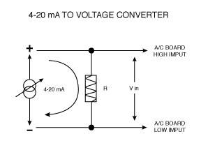
It is extremely simple and inexpensive to measure 4-20 mA with a device that will measure only voltage. Most A/D boards will accept a 0 to 5 Vdc signal, but may not accept a 4-20 mA signal directly. The solution to this problem will only take a few minutes and a few dollars. Basically, Ohm's law is used to calculate a resistor value in order to convert the 4-20 mA to a voltage.
The most popular resistor value for this purpose is 250 Ω, since it will produce a 1 to 5 Vdc signal when 4-20 mA flows through it – and a 0 to 5 Vdc input is very common for most DAQ systems and other analog measurement devices.
However, there are cases where voltage inputs other than 0 to 5 Vdc are desired, so the following example will demonstrate how simple it is to calculate the correct value resistor for any voltage input.
Example

For this example, we will assume that a 0 to 2 Vdc input will be used to measure 4-20 mA.
Ohm's law states: R = V/I – where V is the voltage, I is the current, and R is the resistance.
R = 2V/0.020A = 100 Ω
When 20 mA flows through a 100 Ω resistor, it will drop 2 volts.
When 4 mA flows through a 100 Ω resistor, it will drop 0.4 volts. Therefore, 4-20 mA through a 100 Ω resistor will drop 0.4 to 2 volts.
One more important thing to remember is that the resistor tolerance should be 1% or less; preferably 0.1% since errors in the resistance will result in errors in the voltage drop. You don’t want a resistor that fluctuates much with time or temperature, as it will affect your accuracy. After you have selected a resistor value, you must verify your readings and make any fine-tuning adjustments in your software to compensate for any errors in the resistor. For example, a 100 Ω resistance may actually be 99.5 Ω; therefore, your voltage output will actually be 0.398 to 1.99 V – and not 0.4 to 2 V as we calculated.
You simply connect the resistor across the voltage input terminals for your DAQ system, and then connect your 4-20 mA signal to the same two terminals, so that as the current flows through the resistor, a voltage will be dropped and then measured by the DAQ device. Keep in mind that it may be necessary to ground the power supply if you are using it to power a transmitter or 2-wire sensor.

