Appelez-nous au 1-888-826-6342
304 SS Turbine Flow Meter with Signal Conditioning Option
Turbine Flowmeters with Economical Ball Bearing Design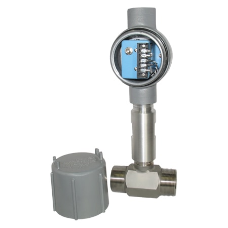
Ajouté à votre panier
Configuration terminée.
Veuillez ajouter au panier pour la conserver ou quitter la configuration
Veuillez ajouter au panier pour la conserver ou quitter la configuration
Échec de l'enregistrement des configurations, cliquez sur le bouton Configurer Recommencer
- NIST Certificate Included for Water
- ±1/2% Rdg Accuracy
- Non-Metallic Bearing Retainers for Long Life
- Replacement Bearings Field Installable Without Loss of Calibration
FTB-102 Options de modèles
Voir tous les modèlesModifiez ces spécifications pour commander un modèle différente. Toutes les combinaisons ne sont pas valides. Les options compatibles avec les sélections précédentes seront en gras.
*Les options en surbrillance ne sont pas compatibles. Veuillez sélectionner une combinaison différente.
Flow Range
Max Operating Pressure
Process Connection Size
Category
Media type
Accuracy
Output Signal
Max Process Temperature
Wetted Materials
Process Connection Type
Display
The FTB-100 Series of turbine meters have a sealed ball bearing design for high accuracy performance (±½% of reading, not full scale) at an economical cost. The non-metallic bearing retainers minimize friction, thereby allowing these meters to be used with clean fluids that have poor lubricating properties ( i.e.water). Ball bearings also give the widest linear flow range, particularly in larger turbines. Bearing replacement and clean-up are fast and easy, since all internal parts are easily accessible by removing a single nut.
These turbine flowmeters have a low mass rotor design which allows rapid dynamic response, so they can be used in pulsating flow applications. Deflector cones eliminate downstream thrust on the rotor and allow hydrodynamic positioning of the rotor between the cones. This provides wider rangeability and longer bearing life than conventional turbine flowmeters. Integral flow-straightening tubes minimize the effects of upstream turbulence.
FTB-100 Turbine Meters are available with integral signal conditioners (as shown in photo) which provide scaled and unscaled frequencies, 4-20 mA, or 0-5 Volt outputs. Units without integral signal conditioners are supplied with mating connector for two-wire hook-up.
SPECIFICATIONS
Accuracy: ±½% of reading
Repeatability: ±0.1% of reading
Maximum Temperature Range: -268 to 232°C (-450 to 450°F)
Maximum Intermittent Overrange: 150% of maximum range
Minimum Output Amplitude: 30 mV Peak-to-Peak Unscaled Pulse
Materials of Construction:
Body: 304 stainless steel; 1/2 NPT bodies contain Silver Solder. 3/4 NPT and larger are welded.
Rotor: 17-4 pH steel
Bearings: Ceramic
Minimum straight pipe requirements: 10 pipe diameters upstream, 5 downstream
| Model No. | Fittings | Linear Flow Range Water | Max Operating Pressure | Max Pressure Drop | Length mm (in) | Nominal K-Factor Pulses/Gal | Weight kg (lb) | |
|---|---|---|---|---|---|---|---|---|
| LPM | GPM | |||||||
| FTB-101 | ½ MNPT | 1.32 to 13.2 | 0.35 to 3.5 | 5000 psig | 3.0 psid | 62 (2.45) | 13,000 | 0.4 (1) |
| FTB-102 | ½ MNPT | 2.84 to 28.4 | 0.75 to 7.5 | 5000 psig | 5.0 psid | 62 (2.45) | 10,000 | 0.4 (1) |
| FTB-103 | ½ MNPT | 4.73 to 36 | 1.25 to 9.5 | 5000 psig | 5.2 psid | 62 (2.45) | 6,000 | 0.4 (1) |
| FTB-104 | ¾ MNPT | 6.62 to 61 | 1.75 to 16 | 5000 psig | 3.0 psid | 70 (2.75) | 4,100 | 0.4 (1) |
| FTB-105 | ¾ MNPT | 9.5 to 110 | 2.5 to 29 | 4250 psig | 5.0 psid | 83 (3.25) | 2,200 | 0.4 (1) |
| FTB-106 | 1 MNPT | 15 to 227 | 4 to 60 | 3850 psig | 5.1 psid | 89 (3.5) | 640 | 0.9 (2) |
| FTB-107 | 1¼ MNPT | 23 to 352 | 6 to 93 | 3850 psig | 4.3 psid | 99 (3.88) | 410 | 0.9 (2) |
| FTB-108 | 1½ MNPT | 30 to 492 | 8 to 130 | 3000 psig | 3.0 psid | 111 (4.38) | 230 | 1.4 (3) |
| FTB-109 | 2 MNPT | 57 to 852 | 15 to 225 | 2500 psig | 3.3 psid | 121 (4.75) | 120 | 1.8 (4) |
| FTB-110 | 2½ MNPT | 95 to 1514 | 25 to 400 | 2250 psig | 4.0 psid | 154 (6.06) | 62 | 2.3 (5) |
| FTB-111 | 3 MNPT | 151 to 2460 | 40 to 650 | 2000 psig | 4.0 psid | 191 (7.50) | 55 | 3.2 (7) |
 RoHS 2015/863 - Voir le certificat
 Approuvé CE
 UKCA
UKCA
Do any of the electrical connections have an electrical connection with the housing? Is it isolated? I'm using with a piece of equipment that requires an SELV power supply and equipment. The housing will be PE grounded.
The self powered flow meter does not come with an electrical housing. The body of the flow meter needs to be grounded if used in a noisy environment.
Date published: 2020-06-03
1. Can the FLSC-C1-LIQ be mounted remotely from the FTB-101? Need to locate the signal conditioner away from the turbine meter due to high ambient temperature. 2. How is the FTB-101 wired-connector or pigtail? If pins, what connector is required?
Thank you for your inquiry. It is recommended not to separate the signal conditioner from the flow meter and in the event that it must, you can add 2-wire shielded cable from the 2 PINS of the turbine flow meter to reduce the electrical noise.
Date published: 2023-03-10
Are any of the pins electrically connected with the body of the flow meter or housing the signal conditioner sits in?
Thank you for your inquiry about this flow meter. The turbine flow meter and signal conditioner are recommended to be purchased as a 'SYS' or system and they are scaled together to be used when received. And the flow meter is connected directly to the signal conditioner.
Date published: 2020-06-08
What is the maximum viscosity for use of a turbine meter
The turbine flow meter has a maximum viscosity noted on the data sheet to be 299 cST (or centiStokes) which is a unit of measure for viscous liquids.
Date published: 2020-02-21