Appelez-nous au 1-888-826-6342
HBM Strain Gauges for High Temps & Alternating Load Resistance
OMEGA/HBM Strain Gages | High Temperature and Resistance to Alternating Loads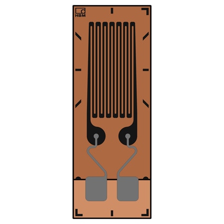
Remises de volume disponibles
Calendrier de remise sur volume
| Quantité | Prix unitaire |
|---|---|
| 1-4 | C$310.14 |
| 5-9 | C$294.63 |
| 10-24 | C$288.43 |
| 25-49 | C$276.02 |
| 50-99 | C$269.82 |
| 100+ | C$263.62 |
Ajouté à votre panier
Configuration terminée.
Veuillez ajouter au panier pour la conserver ou quitter la configuration
Veuillez ajouter au panier pour la conserver ou quitter la configuration
Échec de l'enregistrement des configurations, cliquez sur le bouton Configurer Recommencer
- High Resistance to Alternating Loads
- High Temperature Range 300°C (572°F)
- Wide Spectrum of Different Types
- All models sold in a 5-pack, except 1-LM11 which are sold in a 10-pack
1-LM11-6/350GE Options de modèles
Voir tous les modèlesModifiez ces spécifications pour commander un modèle différente. Toutes les combinaisons ne sont pas valides. Les options compatibles avec les sélections précédentes seront en gras.
*Les options en surbrillance ne sont pas compatibles. Veuillez sélectionner une combinaison différente.
Grid Style
Grid Length Range
Grid Length
Grid Width
Temperature Range Units
Temperature Range Min
Temperature Range Max
Connection Type
Resistance
Maximum Strain
Features
Linear Pattern Strain Gages are the most straightforward geometry of strain gauge, designed to indicate strain in only a single direction.
M Series strain gauges have been specially developed for high resistance to alternating loads at increased strain levels and high temperatures up to 300°C (572°F). They are foil strain gauges with measuring grids made of a special nickel-chromium alloy. OMEGA/HBM offer this special strain gauge with various geometries, measuring grid lengths and temperature response matching.
New materials offering high strength such as fiber composites pose a major challenge for strain gauges used for measurements specifically when pushing components to their mechanical limit of performance. Situations may arise where a strain gauge subjected to alternating loads at increased load levels is weakened and fails earlier than the component under test. The M Series has been specially developed for high resistance to alternating loads and allows for testing of materials featuring high strength.
All M Series strain gauge types are available with different measuring grid lengths:
• 1.5 mm: where space is a constraint or when highly selective measurement results are required
• 3 mm: for inhomogeneous materials and where space is a requirement or not
• 6 mm: for inhomogeneous materials and where space is not a requirement
The right measuring grid length: The measuring grid length depends on the aim of measurement, since the result of a measurement with strain gauges will be determined as the average of strains. In general, measuring grid lengths of 3 to 6 mm (0.06 to 0.24') generates a better result.
Long measuring grids are recommended where there is an inhomogeneous material such as concrete or wood. A long strain gauge will bridge the inhomogeneity of the work piece and return the strain underneath the measuring grid as the measurement result.
Short measuring grids are suitable for detecting a local strain state. Therefore, they are suitable for determining strain gradients, the maximum point of notch stresses and similar stresses.
Specifications
Strain Gage Construction–Foil Strain Gauge
Carrier:
Material: Glass fiber reinforced phenolic
Thickness: 35 ±10 µm
Grid Foil:
Material: CrNi
Thickness: 5 µm
Encapsulation:
Material: Polyimide film
Thickness: 25 ±5 µm
Connections: Solder pads with strain relief
Resistance: 350 and 1000 Ω
Resistance Tolerance: ±0.3%(1)
Gage Factor: Approximate 2.2 (specified on each package)
Gage Factor Tolerance: ±1.5% (for grid length <3 mm) ±0.7% (for grid length ≥3 mm)
Temperature Coefficient of the Gauge Factor: Specified on each package
Transverse Sensitivity: Specified on each package
Operating Temperature Range: -200 to 300°C (-328 to 662°F)
Temperature Response (Ferrite Steel): 10.8 ppm/K (6.0 ppm/°F)
Maximum Elongation:
Positive Direction: 10,000 µm (1%)
Negative Direction: 15,000 µm (-1.5%)
Minimum Bending Radius: 5 mm (0.20') for linear gauges 10 mm (0.39') for stacked rosettes
Bonding Material that Can Be Used: Z70 or EP310S
Fatigue Life (Test to Failure):
107 cycles at 2000 µm/m
106 cycles at 2200 µm/m
104 cycles at 3100 µm/m