Appelez-nous au 1-888-826-6342
DIN Rail Thermocouple Input Signal Conditioners
Thermocouple Input Signal Conditioner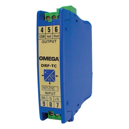
This product has been discontinued. For a potential alternate, please see DRSL-TC.
- Models for J K E T R and S Thermocouples
- Accuracy 0.3%
- 250 ms Response Time
- Upscale Break Protection
- Linearized Output
- Galvanic Isolation Between Input Output and Power
The DRF series DIN rail signal conditioners are designed to accept a broad range of input signals, such as ac and dc voltage and current, frequency, temperature (thermocouple and RTD), and process transducers, and provide standard process outputs of either 4 to 20 mA, or 0 to 10 Vdc. The DRF series feature a modern housing design, that is easily mounted on standard 35 mm DIN rails. Connections are safely and securely made through pluggable screw terminal connectors, with input and output connections on the opposite sides of the module.
The DRF-TC thermocouple signal conditioners accept thermocouple input and provide a linearized and isolated 0 10 Vdc or 4 to 20 mA output. Models are available with three different power options, 24Vdc, 120 Vac and 240 Vac.
The DRF-TC are ideally suited for industrial applications. All models mount on a standard 35 mm DIN rail and provide galvanic isolation between input, output and power up to 3500 Veff (model specific). To insure maximum measurement accuracy the units feature cold junction compensation, 0.2% linearity and less than 0.1°C/1°C thermal drift due to compensation. Module response time is 250 ms or less.
Range Code Table for DRF-TC
* Custom ranges may be obtained by adjusting on-board zero and span potentiometers.
The minimum range is limited by the minimum span specification.
The DRF-TC thermocouple signal conditioners accept thermocouple input and provide a linearized and isolated 0 10 Vdc or 4 to 20 mA output. Models are available with three different power options, 24Vdc, 120 Vac and 240 Vac.
The DRF-TC are ideally suited for industrial applications. All models mount on a standard 35 mm DIN rail and provide galvanic isolation between input, output and power up to 3500 Veff (model specific). To insure maximum measurement accuracy the units feature cold junction compensation, 0.2% linearity and less than 0.1°C/1°C thermal drift due to compensation. Module response time is 250 ms or less.
Range Code Table for DRF-TC
| Range Code | Range | J | K | T | E | R | S |
| 0/100°C | 0 to 100°C | X | |||||
| 0/150°C | 0 to 150°C | X | X | ||||
| 0/175°C | 0 to 175°C | X | |||||
| 0/200°C | 0 to 200°C | X | |||||
| 0/250°C | 0 to 250°C | X | X | ||||
| 0/300°C | 0 to 300°C | X | X | ||||
| 0/400°C | 0 to 400°C | X | X | X | |||
| 0/500°C | 0 to 500°C | X | |||||
| 0/700°C | 0 to 700°C | X | X | ||||
| 0/800°C | 0 to 800°C | X | |||||
| 0/1200°C | 0 to 1200°C | X | |||||
| 0/1600°C | 0 to 1600°C | X | |||||
| 850/1700°C | 850 to 1700°C | X | |||||
| Minimum Span* | 85°C | 85°C | 100°C | 85°C | 100°C | 100°C |
The minimum range is limited by the minimum span specification.
| SPECIFICATIONS Accuracy: <0.3% full scale Linearity: <0.2% full scale Thermal Drift: 250 ppm/°C typical Thermocouple CJC Drift: 0.1°C/°C Response Time: <250 mS (90% of signal) Power: 24 Vdc ±10%, 230 Vac ±10% 50/60 Hz, 115 Vac ±10% 50/60 Hz Power Consumption: <3.8 VA Output: 4 to 20 mA and 0 to 10 Vdc Maximum Voltage Output: 11 Vdc approx. Minimum Voltage Output: -1 Vdc approx. Minimum Load Resistance (Voltage): >1 KΩ Maximum Current Output: 22 mA approx. Maximum Current Output: -1.5 mA approx. Maximum Load Resistance (current): >400 Ω | Electrical Connections: Plug-in screw terminals Protection: IP-30 MECHANICAL DIMENSIONS Weight: (DC Powered Models): 120 g (4.2 oz) (AC Powered Models): 200 g (7 oz) Dimensions: (DC Powered models): 110 H x 22.5 W x 93 mm D (4.3 x 0.9 x 3.7") (AC Powered models): 110 H x 37 W x 93 mm D (4.3 x 1.46 x 3.7") Operating Temperature: 0 to 60°C (32 to 140°F) Storage Temperature: -20 to 70°C (-4 to 158°F) |
 RoHS 2015/863 - Voir le certificat
 Approuvé CE